

Austrian Delights
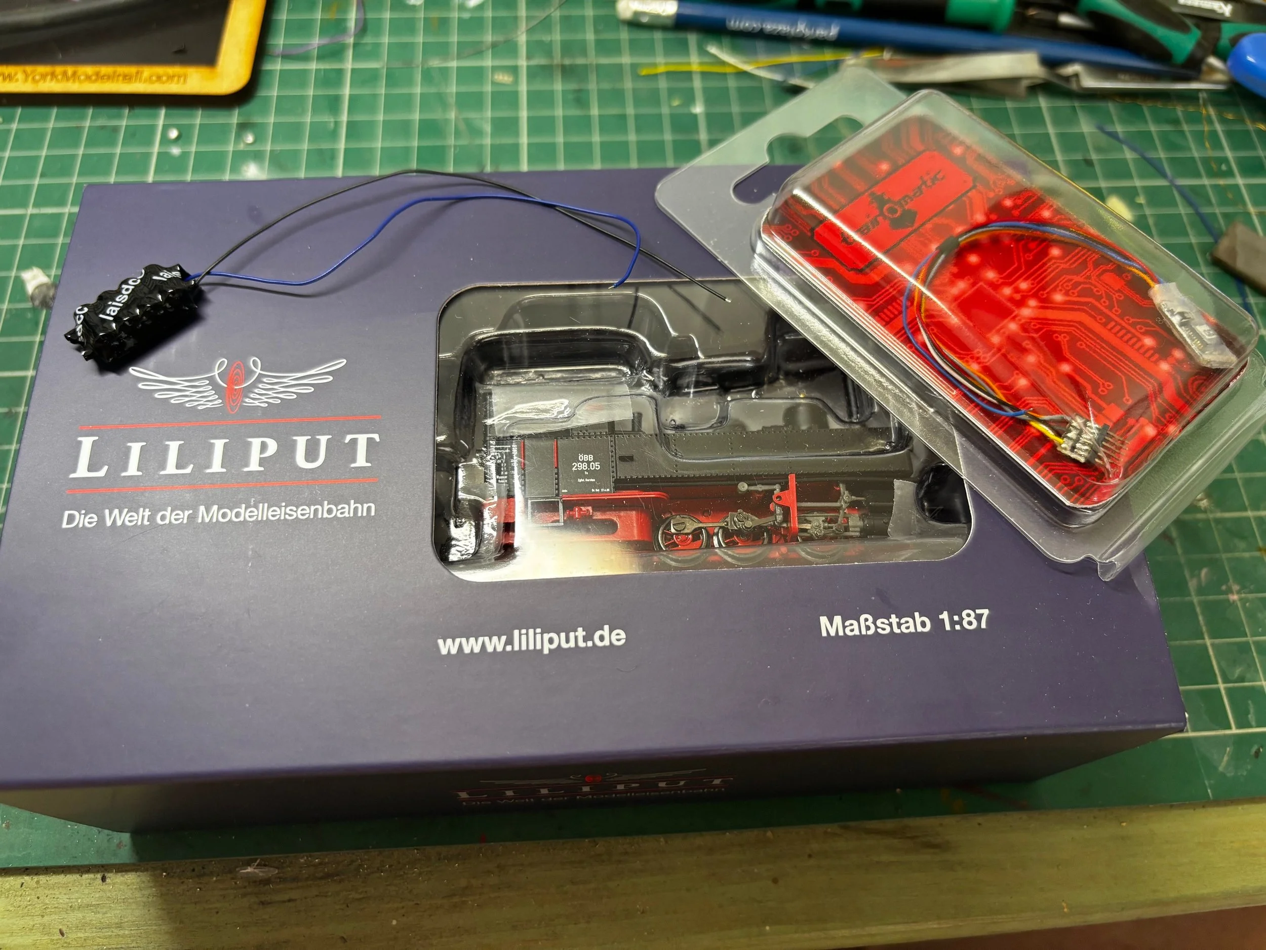
I do occasionally enjoy a challenge, and when it comes to fitting DCC decoders, challenges usually mean something small. This small challenge comes in the form of Liliput’s charming HOe U type 0-6-2 tank engine.
I was asked by a friend and fellow operating team member, John, if I would mind fitting dcc decoders to three of his U type steam locos. I had wanted to have a crack at one of these for a while, so I immediately said yes.
After receiving the three locos and giving them all a good test and running in session, it was time to make a start. I had previously discussed with John if he had any preferences to what decoders he wanted in them. I always find this to be an essential conversation when carrying out these task for others, as they may have a preference for a particular brand. Cost is also an important consideration for all of us as well.
I recommended the Micro 6 decoder from Train-O-Matic, and John was happy to trust my recommendation. I have used Train-O-Matic decoders in my own models, and I have always found them to be excellent value. They have very good motor control characteristics and for their price they are hard to beat. We also discussed and agreed on the fitting of a stay-alive as well, us these mini locos have quite a short wheelbase, and would in my opinion benefit from having one fitted. For this I decided on a Lais DCC Kungfu Lite, which was a spot on fit in the cab.
Getting Inside
Fitting of a decoder into anything always starts with actually gaining access to the inside of the model These Liliput are easy enough the get into, just gently lever up the water tank hatch on each side, the gently lever up the bottom rear edge of the cab back from the chassis and bob’s your uncle! we can now see all the gubbins inside.

Now What?
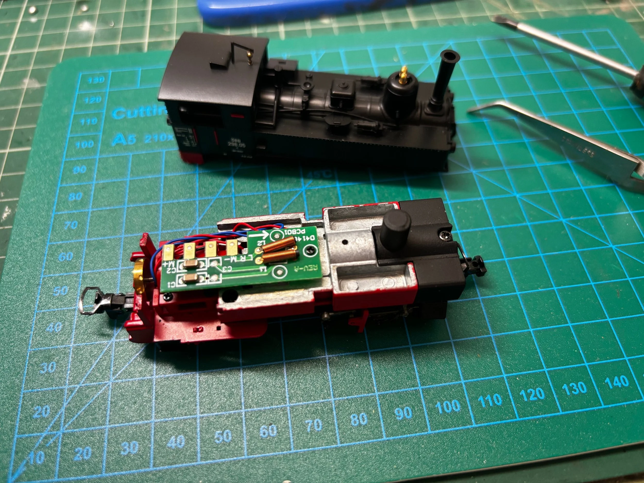
Now that we can see what we have to work with, we can plan the installation. The cab had nice amount of space available, but squeezing the decoder and stay-alive in there would have been a bit messy in my opinion, so the stay-alive would fit nicely in the cab, and the decoder would go where the original circuit board sits at the moment.
I do find that with models that are not DCC ready (and sometimes with ones that are) the easiest way is to junk the original circuit board and ‘hard wire’ the decoder. Care needs to be taken when considering this method as if the model is within the manufacturer’s warranty period, getting rid of their bits will void any warranty!
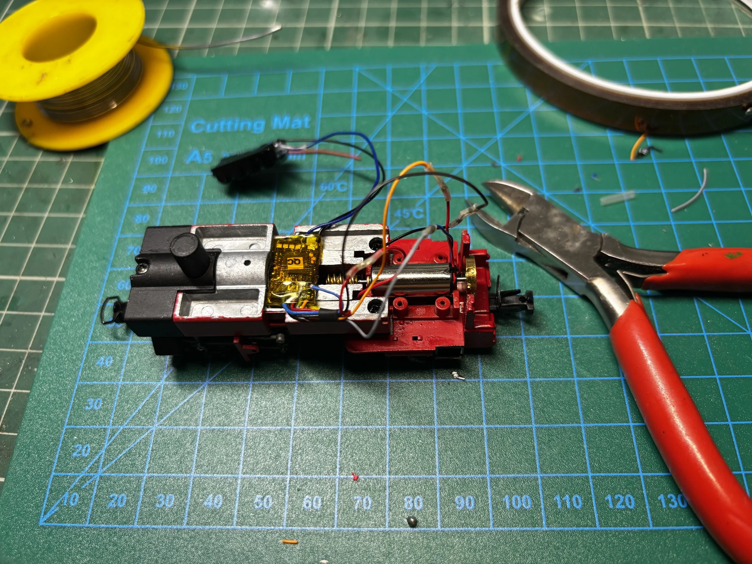
With the circuit board removed, we have two wires (red and black) coming from the pick ups and two going to the motor (red and blue). There is also a nice little recessed area in the top of the chassis block that would accept the decoder, so that looks good.
The slight issue was the two locating pegs and the screw stand-off for the original pcb. This was the point on no return! I knew John didn’t ever want the loco to be put back to factory (DC powered), so the Dremel came out and the sanding began!
I was careful to remove the motor before this and to block up the slot where the gear sit, so that the metal filings didn’t get anywhere that would cause a problem later. What was left was a nice flat surface for the decoder to sit on.


Time for the Hot Stuff
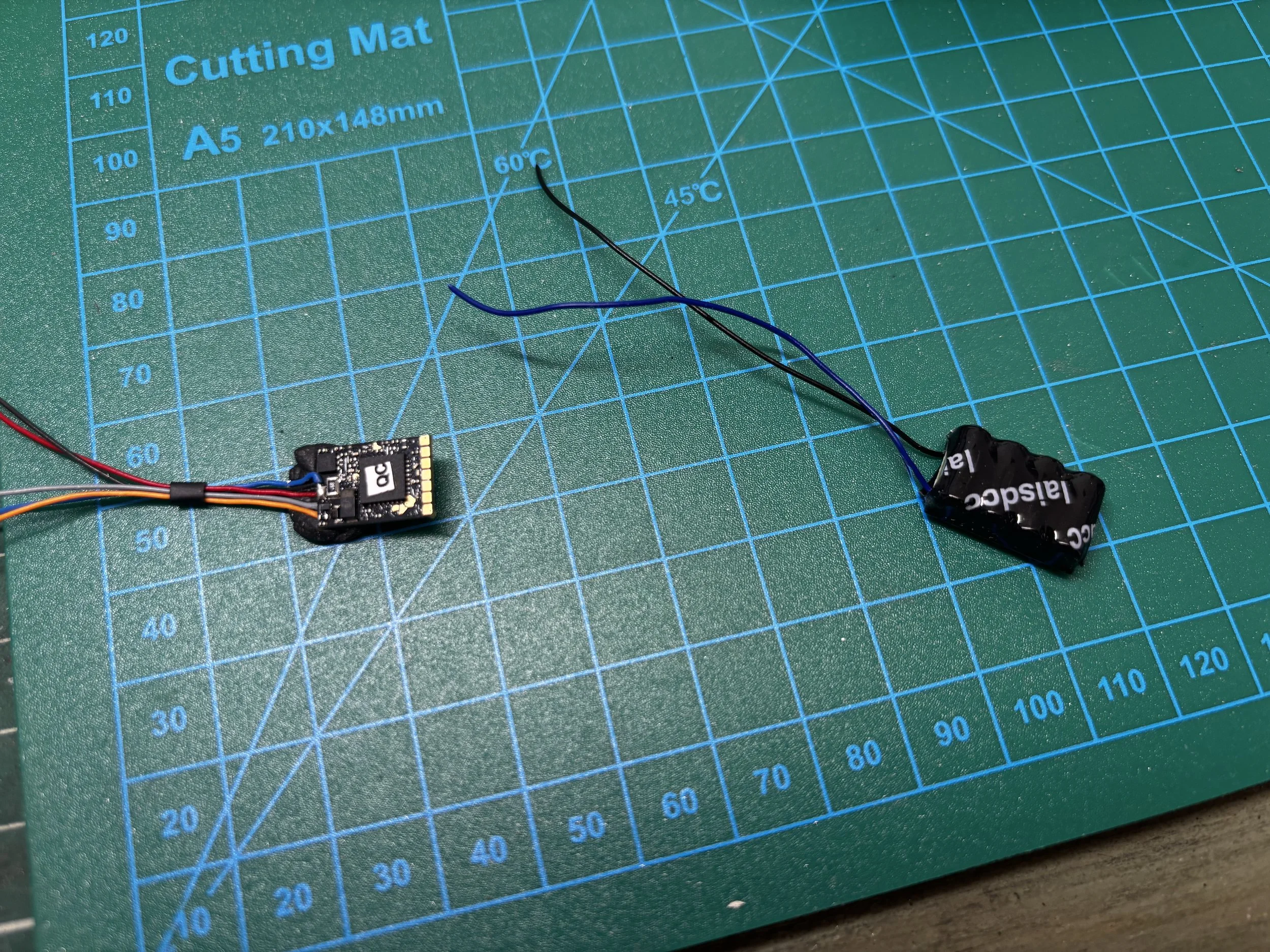
Now I could look at getting things wired up. Given we were still tight on vertical space of our decoder, I took the decision to free it from its quite thick plastic coating that it came with. This needed to be done anyway to attach the stay-alive to the decoder itself. I would however, re-clothe it in a nice thin layer of Kapton tape when all the soldering was finished.
Soldering to any decoder can be a bit daunting, and this feeling can be magnified the smaller the decoder gets. I always like to work with a nice small soldering iron tip, as I find it gives me more precision. Mistakes do happen sometimes, but i’ve always thought that all it takes is to have a bit of courage and just go for it! Regret the things we’ve tried rather than regret not trying at all.
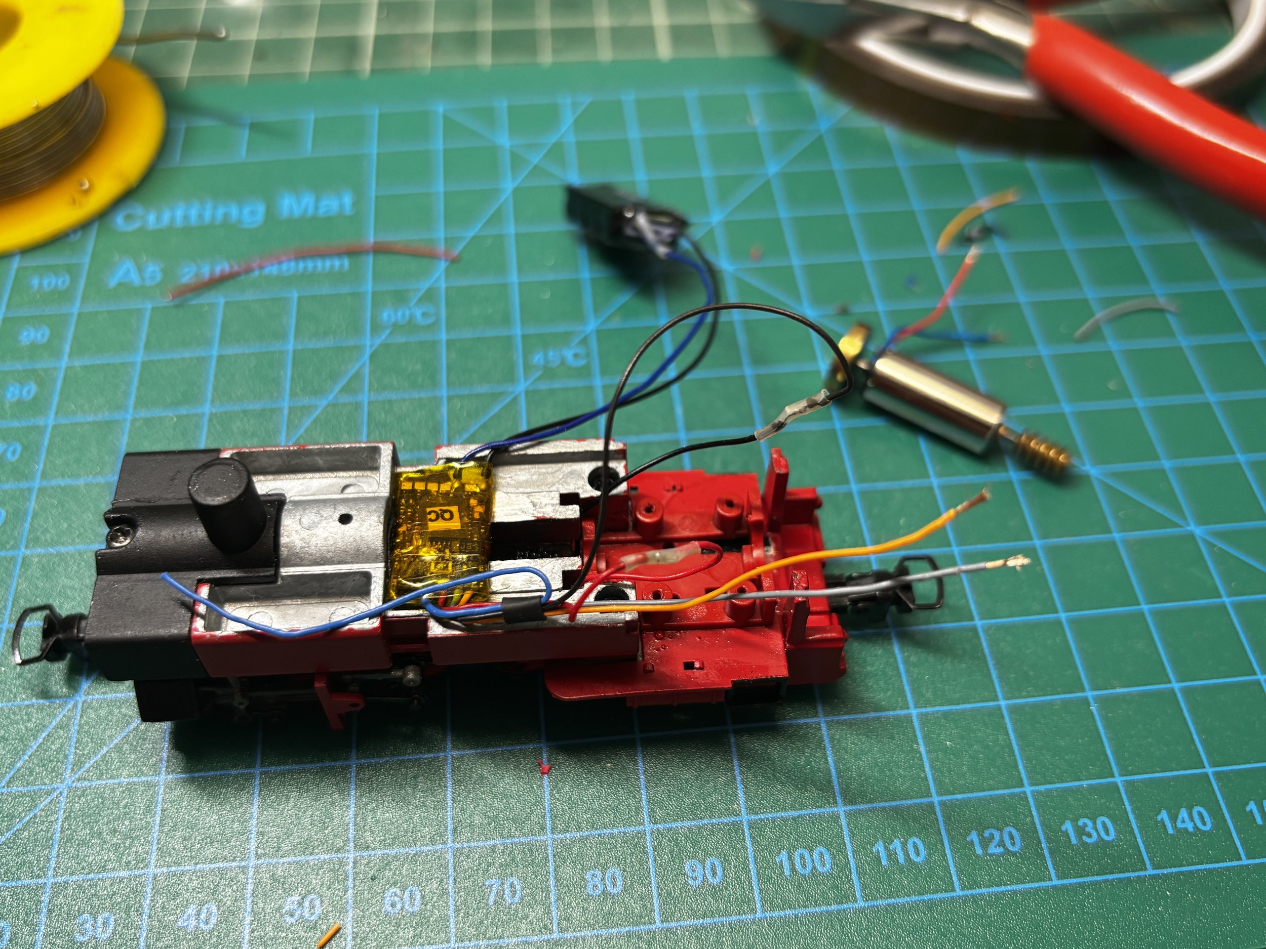
With the stay-alive attached satisfactorily, the decoder was wrapped in Kapton tape and secured in place with the ever reliable black-tac. Then the red and black wires decoder wires were soldered to the red and black pick-up wires, and the orange and grey were soldered to the motor wires and all connections insulated with heat shrink.
The Home Stretch
The motor was secured back in place and while there was easy access, a couple drops of oil were added to the gears. With everything secured, but before the body goes back on, the loco was now tested. One can feel a bit apprehensive at this point as there’s always that first question of ‘will it work?’.
Thankfully everything seemed to be working well. After this there comes what can be the most frustrating part of any decoder installation; getting the body back on!
There have been times in the past, and probably the future as well, where i’ve spent just as long on getting the everything in and getting the body to fit back on. All it takes is a stray wire, and this part can become infuriating.
Thankfully the panning on this project paid off. The stay-aline was secured in the cab roof with our faithful back-tac and all the wiring fitted nicely above and around the motor.
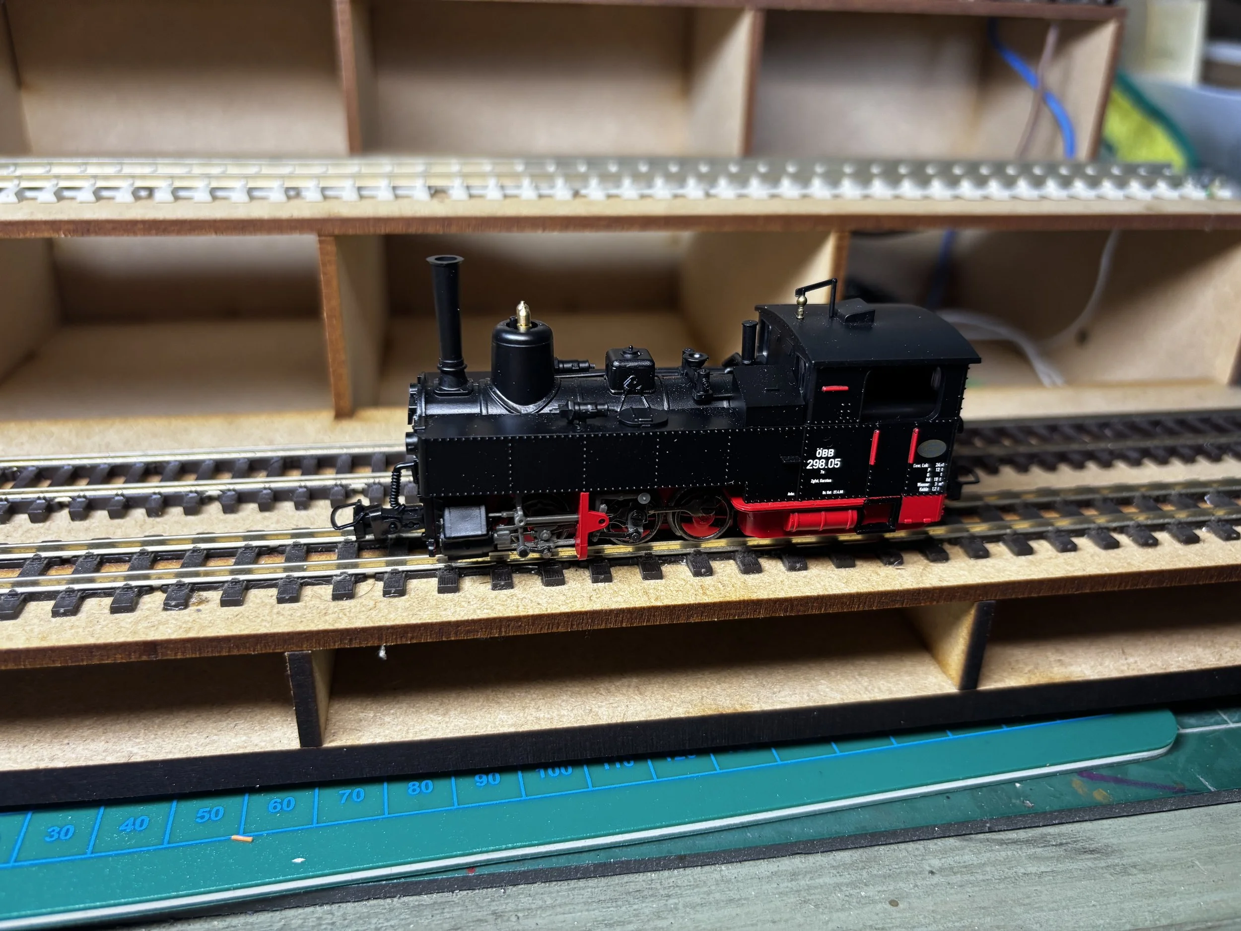
With the body re-attched, a final test was carried out and all was well. The Train-O-Matic decoders have very good settings straight out of box, so I only had to tweak a couple of CV’s and she works a treat!


Final Thoughts
I very much enjoyed this install. This is probably a good thing since I have another two of them to do! After each decoder install I always like to asses things. I always ask myself, ‘if I do this again, would I do anything differently?’. In this case, my answer would be ‘probably’. I would definitely neaten up the decoder wiring, and maybe even detach all the decoder wires from the decoder and wire the pick-up and motor wires directly to the decoder; they’re certainly long enough. I’ll probably give this a go on the other two locos.